Software Modelling and Design
Summary
Table of Contents
Use Cases
- use case: informally: text story of an actor using a system to meet goals
- emphasises user goals and perspective
- who is using the system?
- what are their typical scenarios of use?
- what are their goals?
- formally: collection of related success/failure scenarios that describe an actor using the SuD to support a goal
- primarily capture functional requirements
- define a contract of how a system will behave
- emphasises user goals and perspective
- SuD: system under discussion
- actor: something with behaviour; e.g. person, computer system, organisation
- scenario/use case instance: specific sequence of actions/interactions between actors and SuD
Level of Detail
- brief: terse one-paragraph summary of the main success scenario
- casual: informal multi-paragraph format covering various scenarios
- fully dressed: formal writing of each step and variations in detail, with supporting material
Use case variants
- main success scenario: ideal use case; mandatory element
- “happy path”, typical flow
- usually has no conditions/branching
- alternative scenario: optional, enhances understanding, provides some alternative behaviour
- covered in Extensions section when fully dressed
Actors
- primary actor: has user goals fulfilled through using services of SuD
- supporting actor: provides a service to SuD to clarify external interfaces/protocols
- typically a computer system (e.g. payment authorisation system) but can be an organisation or person
- offstage actor: has an interest in behaviour of the use case, but is not primary/supporting
- e.g. tax agency
- important to include to ensure all stakeholder requirements are captured
Importance
- influences design, implementation, project management
- key source of information for OO analysis/testing
- use cases should be strongly driven by project goals
Use case Model
- Use case model: model of system functionality/environment
- primarily: set of written use cases
- optionally: includes UML use case diagram
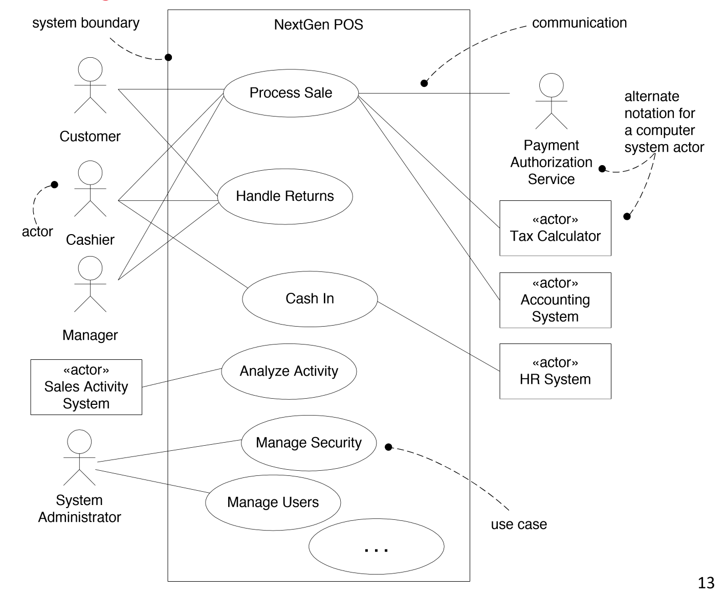
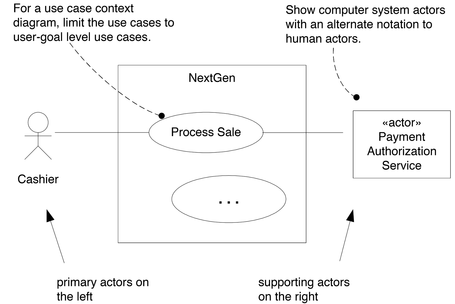
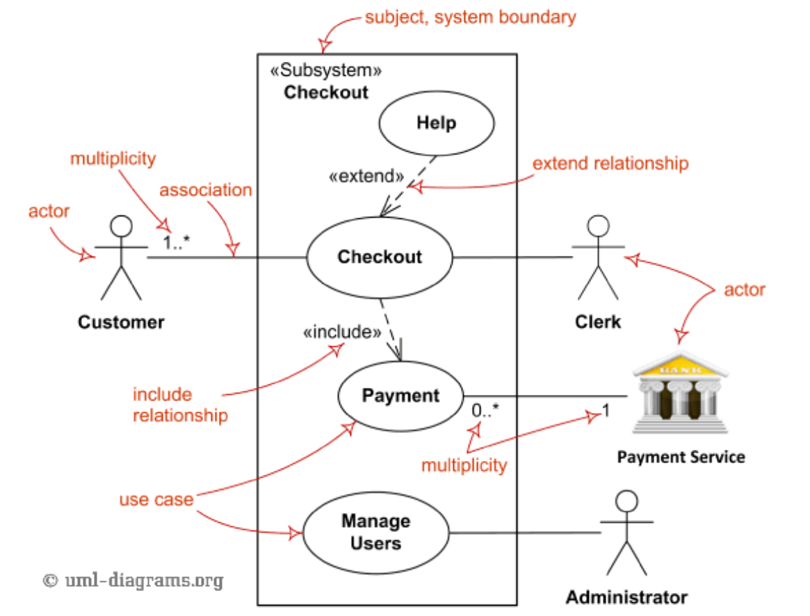
Use case Diagram
- show primary actors on LHS
- show supporting actors on RHS
Relevance of Use cases
To check whether use-cases are at the right level for application requirements analysis, you can apply a number of tests.
- Boss test: your boss must be happy if, when asking you what you have been doing, you respond with the use case
- Elementary business process test: a value-adding process undertaken by one person in one location in response to a business event
- Size test: tasks shouldn’t be a single step. They shouldn’t be too many steps.
- Fully dressed: 3-10 pages
Example:
- negotiate a supplier contract: much broader/longer than an EBP
- handle returns: OK with the boss. Seems like EBP. Good size.
- Log in: fails boss test
- Move piece on game board: single step - fails size test.
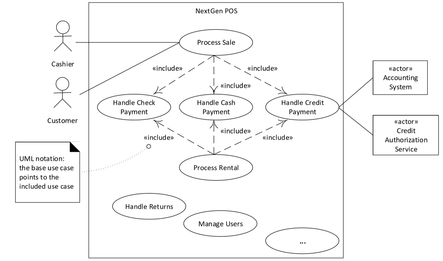
Include relationship
- used to reduce repetition in multiple use cases
- refactor common part of use cases into subfunction use case
Extensions:

6b. Paying by credit: Include Handle Credit Payment.
Extend relationship
- used to add new extensions/conditional steps to a use case
- base case is complete without the extension
- extension relies on base case
- base case doesn’t know about extension
- extension analogous to wrapper or subclass
- used infrequently: most often when you cannot modify the original
- where possible, modify use case text instead
OO Analysis
- OO analysis: creating description of domain from OO perspective
- analyse use cases and identify objects/concepts in problem domain
- concepts/behaviours captured in Domain models and Sequence diagrams
- abstract level of intention
- intended to help understand the domain
- domain models and system sequence diagrams are the primary artefacts
Domain Models
- domain model: representation of real-situation conceptual classes
- not a software object
- shows noteworthy domain concepts/objects
- is an OO artefact
- focus on explaining things and products important to the particular business domain
- represented visually using UML class diagram: show conceptual classes, attributes and associations
- no method signatures defined
- visual dictionary of noteworthy abstractions, domain vocabulary, information content of the domain
- should be recognisable to a non-programmer from the domain
- captures static context of system
- attribute or class?
- if X not considered a number/text in the real world, X is probably a conceptual class, not an attribute
- don’t use attributes as foreign keys: show the association
Identifying conceptual classes
Approaches:
- noun phrase analysis: use carefully, but often suggestive
- use published category list/existing models for common domains
Associations
- association: relationship between classes indicating a meaningful/interesting connection
- include associations when
- significant in the domain
- knowledge of the relationship needs to be preserved
Attributes
- attribute: logical data value of an object
- include when requirements suggest a need to remember information
- do not show visibility: this is a design detail
Creating a Domain Model
- find conceptual classes
- draw as classes in UML class diagram
- add associations and attributes
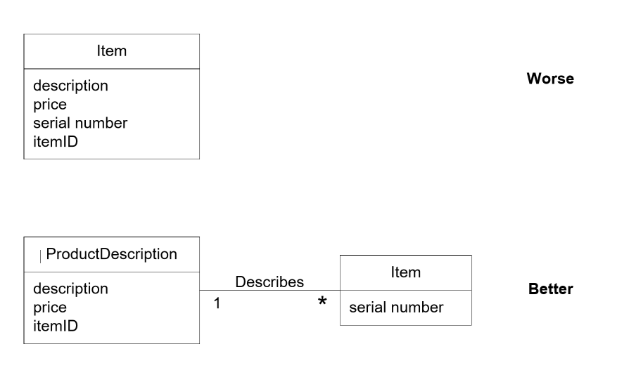
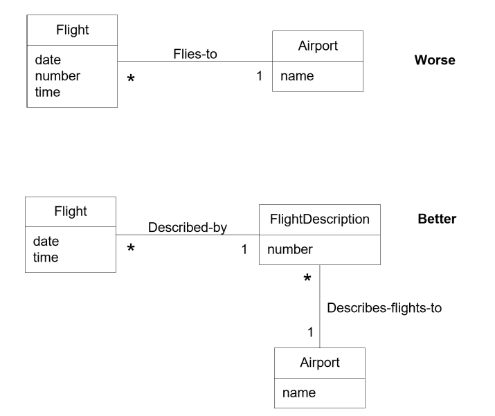
Description Class
- description class: contains information that describes something else
- used when:
- groups of items share the same description
- items need to be described, even when there are currently no instances
System Sequence Diagrams
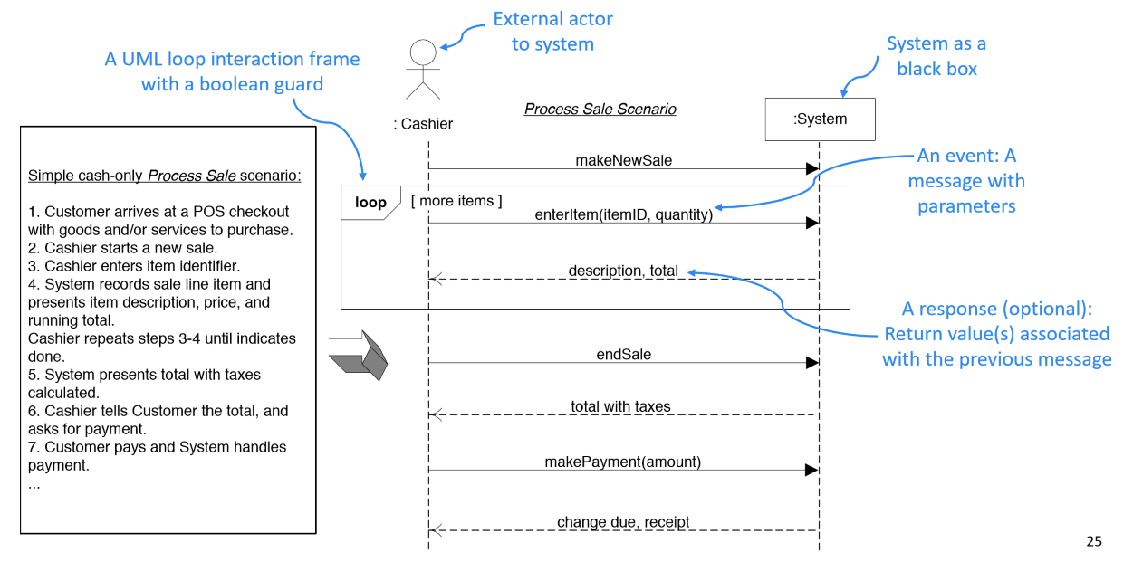
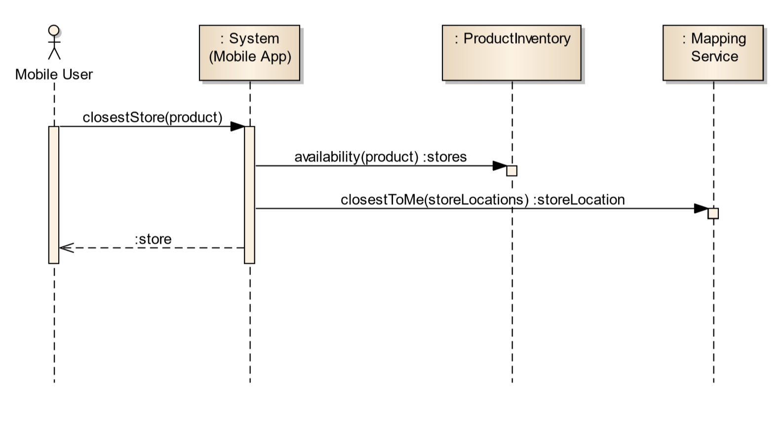
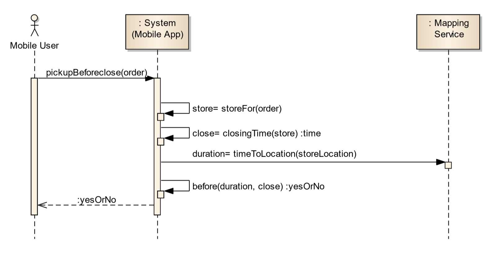
- system sequence diagram: shows chronology of system events generated by external actors
- captures dynamic context of system
- one SSD for one scenario of a use case
- helps identify external input events to the system (i.e. system events)
- indicates events design needs to handle
- treat system as a black box: describe what it does without describing implementation details
- choose system events that don’t tie you to an implementation
- events should remain abstract: show intent, not the means
- e.g.
enterItembetter thanscan
- all external actors (human or not) for the scenario are shown
- can show inter-system interactions, e.g. POS to external credit payment authoriser
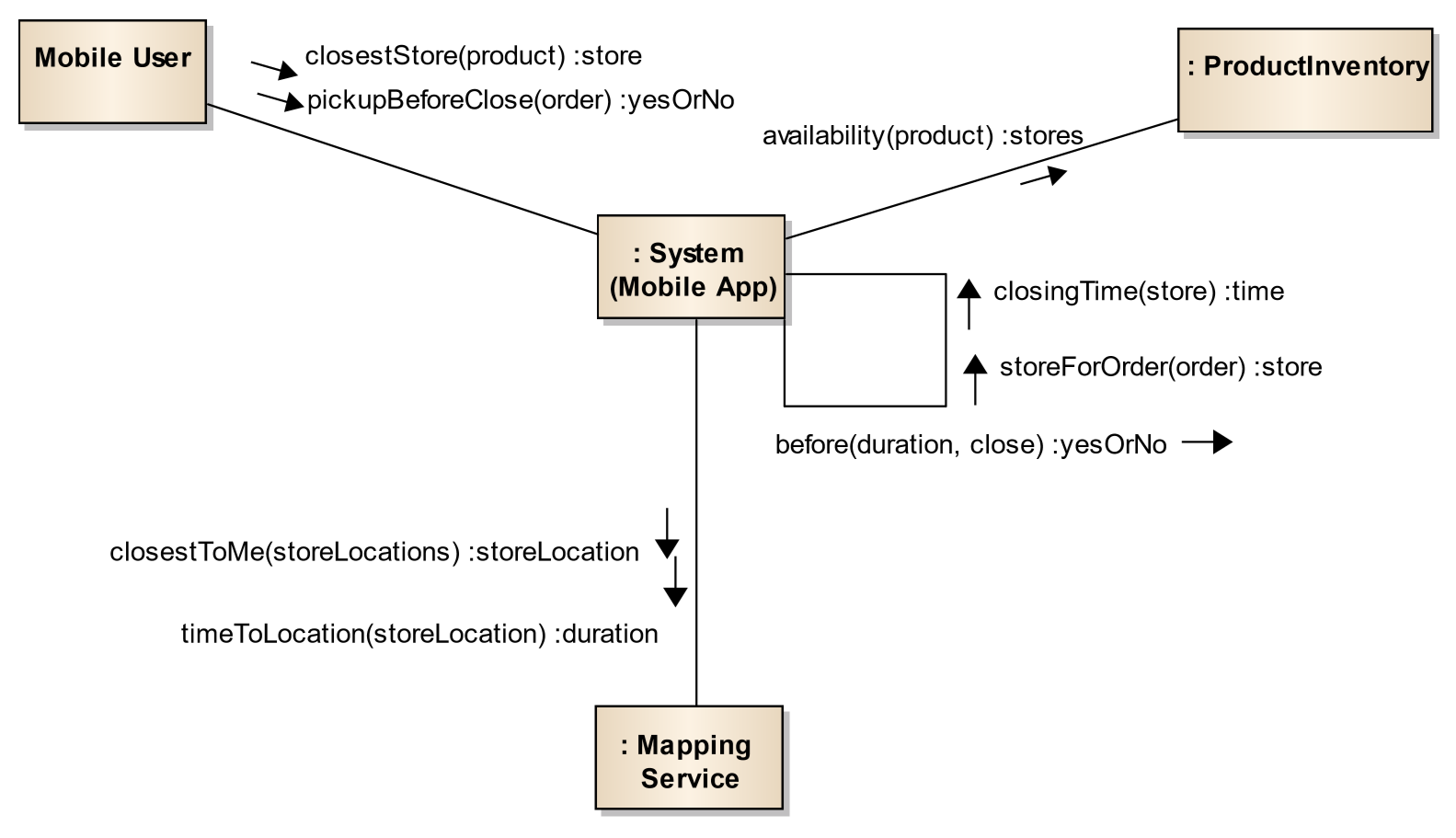
Communication Diagrams
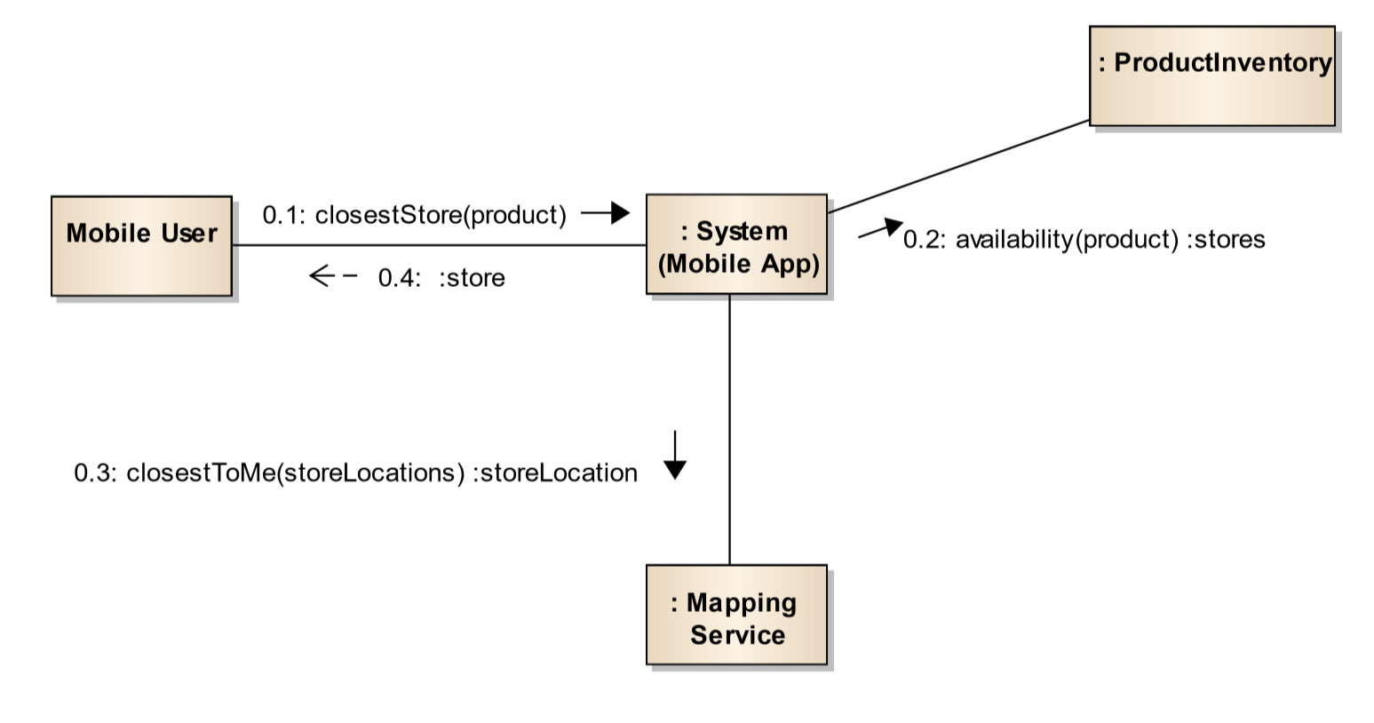
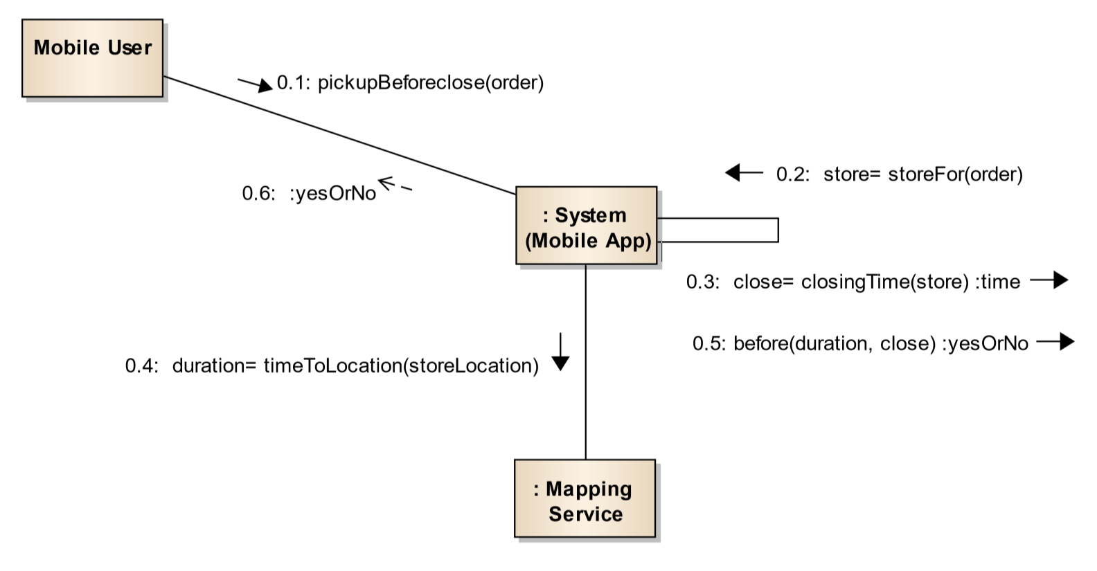
- different way to convey same information as a sequence diagram
Closest Store: System Sequence Diagram vs System Communication Diagram
Pickup before close: SSD vs SCD
Combined System Communication Diagram
Message Sequence Numbers
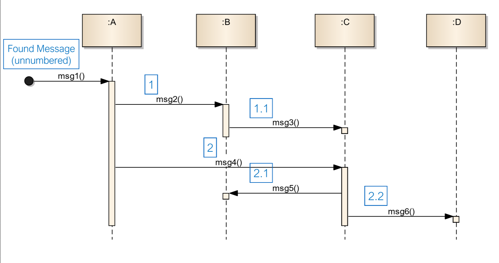
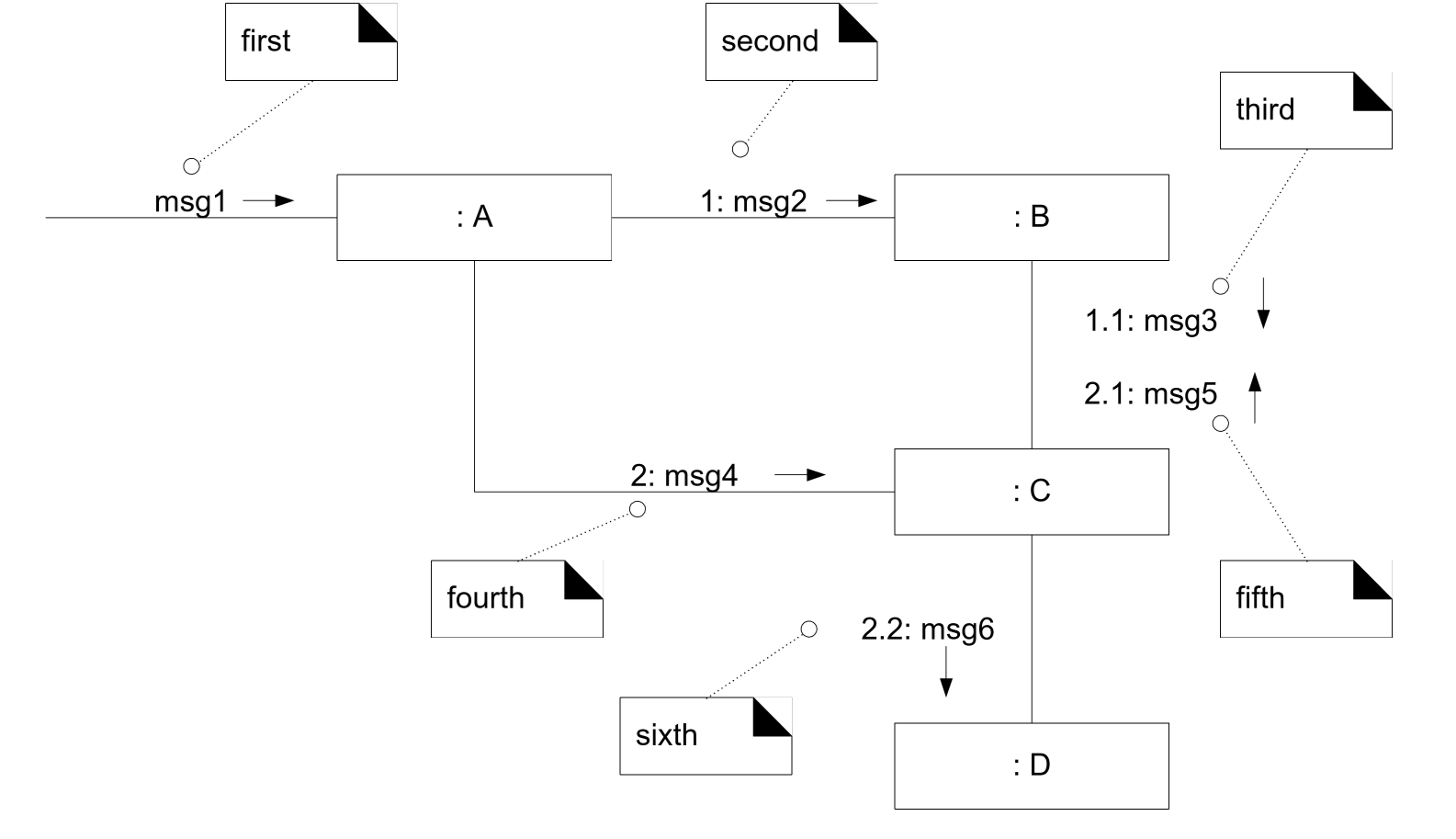
Sequence vs Communication diagram
- sequence:
- pros:
- shows time ordering
- easy to convey details of message protocols
- cons
- linear layout can obscure relationships
- linear layout consumes horizontal space
- pros:
- communications:
- pros:
- clearly show relationships between object instances
- can combine scenarios to provide a more complete picture
- cons:
- more difficult to see message sequencing
- fewer notation options
- pros:
Object-Oriented Design Models
OO Domain Models
- Analysis: investigation of problem and requirements
- OO Software Analysis: finding and describes objects/concepts in the problem domain
OO Design Models
- Design: conceptual solution that meets the requirements of the problem
- OO Software Design: defining software objects and their collaboration
Input Artefacts to OO design
- Use case text describes functional requirements that design models must realise
- Domain models provide inspiration for software objects in design models
- System sequence Diagram indicates an interaction between users and system
OO Software Design
- process of creating conceptual solution: defining software objects and their collaboration
- architecture
- interfaces: methods, data types, protocols
- assignment of responsibilities: principles and patterns
Output Artefacts of OOSD
- Static model: Design class diagram
- Dynamic model: Design sequence diagram
Static Design Models
- static design model: representation of software objects, defining class names, attributes
and method signatures
- visualised via UML class diagram, called design class diagram
Comparison to Domain models
- Domain model: conceptual perspective
- noteworthy concepts, attributes, associations in the domain
- Design model: implementation perspective
- roles and collaborations of software objects
- Domain models inspire design models to reduce the representational gap
- talk the same language in software and domain
Dynamic Design Models
- dynamic design model: representation of how software objects interact via messages
- visualised as UML Sequence diagram or UML Communication diagram
- Design Sequence diagram: illustrates sequence/time ordering of messages between software
objects
- helpful in assigning responsibilities to software objects
SSD vs DSD
- System Sequence Diagram treats the system as a black box, focusing on interactions between actors and the system
- Design sequence diagram illustrates behaviours within the system, focusing on interaction between software objects
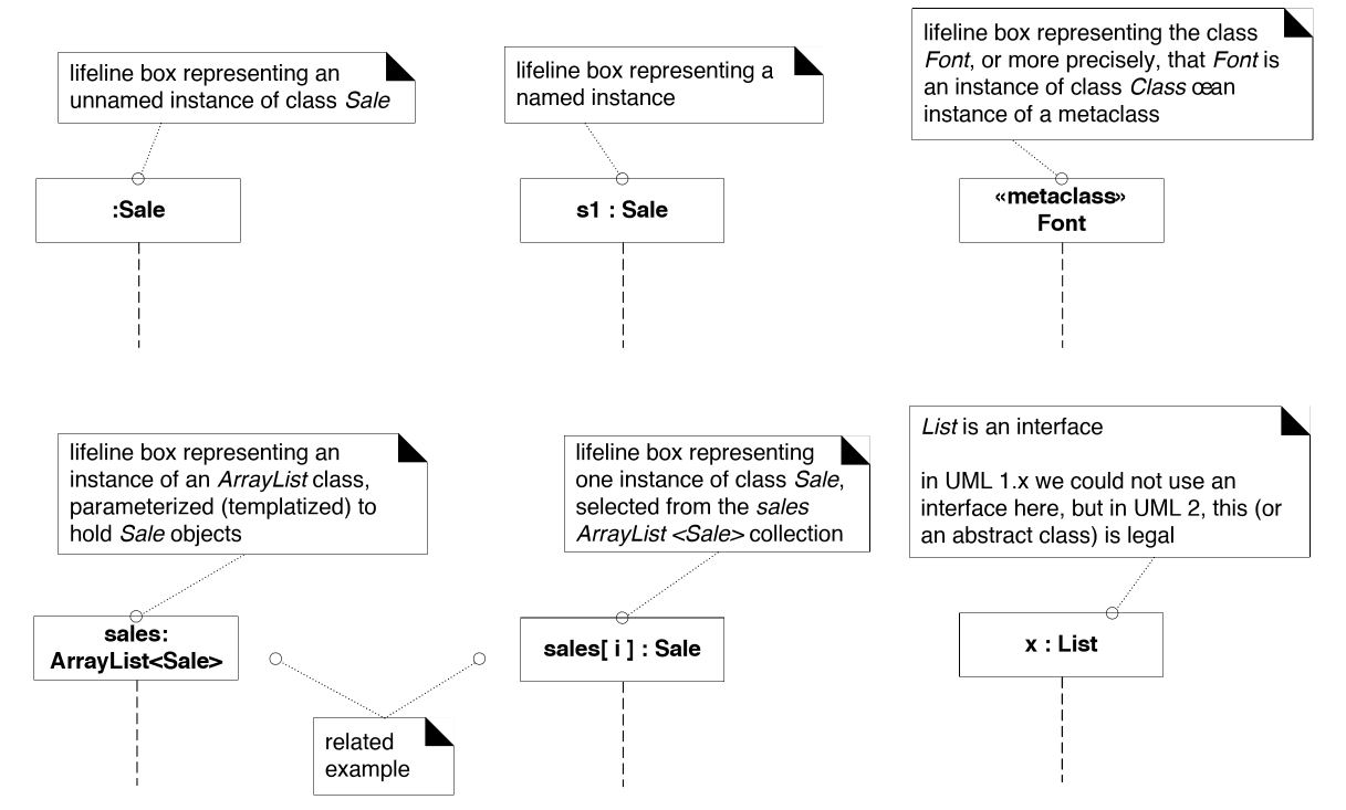
Lifeline Notation
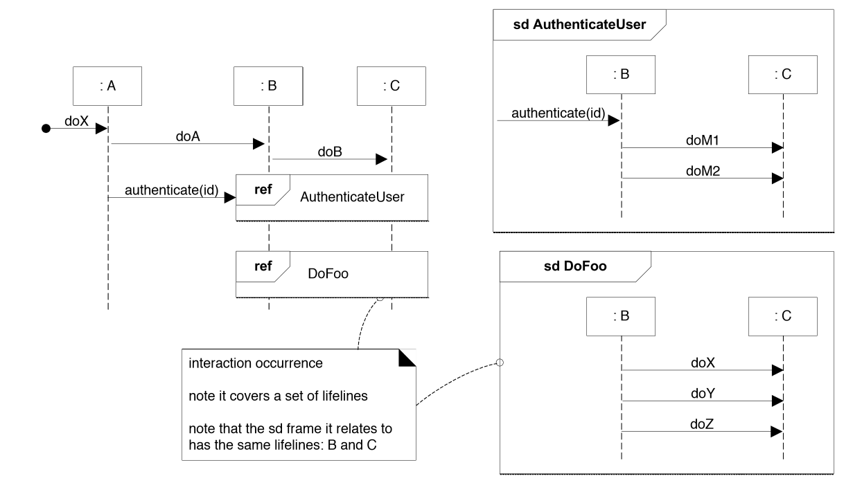
Reference frames
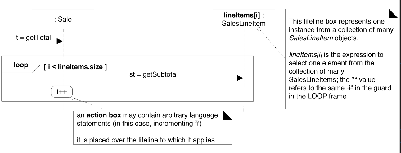
Loop frames
OO Implementation
- Implementation: concrete solution that meets the requirements of the problem
- OO Software Implementation: implementation in OO languages and technologies
Translating design models to code
- build least-coupled classes first, as more highly coupled classes will depend on these
- use
Mapfor key-based lookup - use
Listfor growing ordered list - declare variable in terms of the interface (e.g.
MapoverHashMap)
Visibility
- visibility: ability of an object to see/refer to another object
- objects require visibility of each other in order to cooperate
- e.g. for
Ato send a message toB,Bmust be visible toA
Achieving visibility
A can get visibility of B in 1 of 4 ways:
Bis an attribute ofABis a parameter of a method ofABis a (non-parameter) local object in a method ofABhas global visibility
State Machines
- state machine: behaviour model capturing dynamic behaviour of an object in terms of
- states: condition of an object at a moment in time
- event: significant/noteworthy occurrence that causes the object to change state
- transition: directed relationship between two states, such that an event can cause the object to change states per the transition
- visualised via UML State machine diagram
When to apply state machine diagrams?
- state-dependent object: reacts differently to events depending on its state
- e.g. elevator
- state-independent object: reacts uniformly to all events
- e.g. automatic door
- state-independent w.r.t a particular event: responds uniformly to a particular event
- e.g. microwave state-independent w.r.t cancel
- Consider state machines for state-dependent objects with complex behaviour
- Domain guidance:
- business information systems: state machines are uncommon
- communications/control: state machines are more common (e.g. Berkeley socket)
UML Details
- transition action: action taken when a transition occurs
- typically represents invocation of a method
- guard: pre-condition to a transition
- if false, transition does not proceed

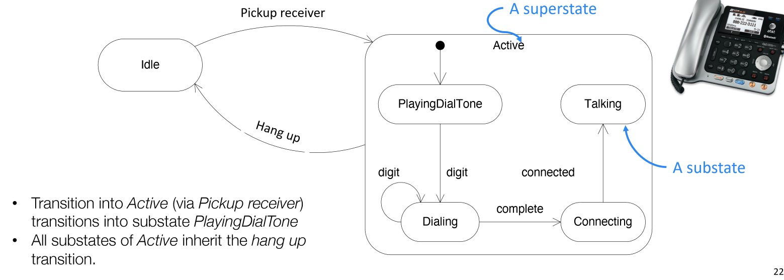
- nested states: substates inherit transitions of the superstate
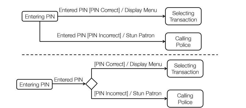
- choice pseudostates: dynamic conditional branch
- can have as many branches as needed
- can use an
[else]branch to follow if no other guards are true
Implementation Details
- use an enumeration for states
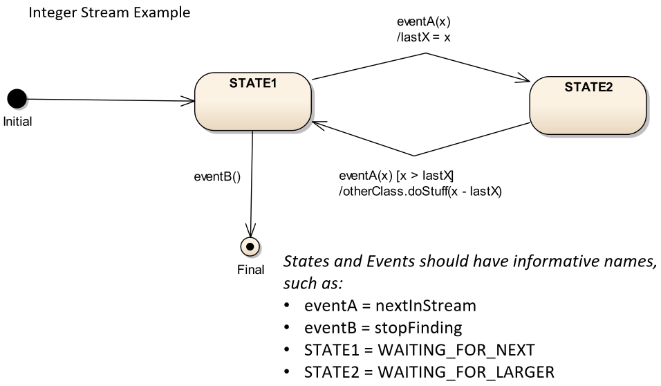
public class IncreasingPairFinder {
  // enum for all the states of the state machine
  enum State { STATE1, STATE2, FINAL }
  // initialise to start state
  State state = State.STATE1;
  int lastX;

  // trigger
  public void eventA(int x) {
    if (state == State.STATE1) {
      // action
      lastX = x;
      // transition
      state = State.STATE2;
    } else if (state == State.STATE2) {
      // condition
      if (x > lastX) {
        // action
        otherClass.doStuff(x - lastX);
        // transition
        state = State.STATE1;
      }
    }
  }

  public void eventB() {
    if (state == State.STATE1) {
      state = State.FINAL;
    }
  }
}
Architecture
- Larman: Chs 13, 33
Software Architecture
- software architecture: large scale organisation of the elements in a software system
- descisions:
- structural elements: what are the components of the system?
- interfaces: what interfaces do elements expose?
- collaboration: how do the elements work together according to the business logic?
- composition: how can elements be grouped into larger subsystems?
Architectural Analysis
- architectural analysis: process of identifying factors that will influence the architecture,
understand their variability and priority, and resolve them
- identify and resolve non-functional requirements in the context of functional requirements
- challenge: what questions to ask, weighing the trade-offs, knowing the many ways to resolve architecturally significant factors
- goal: reduce risk of missing critical factor in the design of a system
- focus effort on high priority requirements
- align the product with business goals
Architectural analysis identifies and analyses:
- architecturally significant requirements: are those which can have a significant impact on the system design, especially if they are not accounted for early in the process
- variation points: variation in existing current system/requirements
- e.g. multiple tax calculator interfaces that need to be supported
- potential evolution points: speculative points of variation that may arise in the future, but are not captured in existing requirements
Architecturally significant functional requirements
- Auditing
- Licensing
- Localisation
- Online help
- Printing
- Reporting
- Security
- System management
- Workflow
Architecturally significant Non-functional Requirements
- Usability
- Reliability
- Performance
- Supportability
Effects of requirements on design
- the answer to the following questions significantly affects the system design
- how do reliability and fault-tolerance requirements affect the design?
- e.g. POS: for what remote services (tax calculator) will fail-over to local services be allowed?
- how do the licensing costs of purchased subcomponents affect profitability?
- e.g. more costly database server weighed against development time
Steps
- start early in elaboration phase
- architectural factors/drivers: identify and analyse architectural factors
- architectural factors are primarily non-functional requirements that are architecturally significant
- overlaps with requirements analysis
- some should have been identified during the inception phase, and are now investigated in more detail
- architectural decisions: for each factor, analyse alternatives and create solutions, e.g.:
- remove the requirement
- custom solution
- stop the project
- hire an expert
Priorities
- inflexible constraints
- must run on Linux
- budget for 3rd party components is X
- legal compliance
- business goals
- demo for clients at tradeshow in 18 months
- competitor driven window of opportunity
- other goals
- extendible: new release every 6 months
Architectural Factor Table
- documentation recording the influence of factors, their priorities, and variability
Fields
- Factor
- Measures, quality scenarios
- Variability: current, future evolution
- Impact of factor to
- stakeholders
- architecture
- other factors
- Priority for success
- Risk
Technical Memo
- records alternative solutions, decisions, influential factors, and motivations for noteworthy issues/decisions
Contents
- Issue
- Solution summary
- Factors
- Solution
- Motivation
- Unresolved Issues
- Alternatives Considered
Logical Architecture
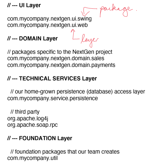
- logical architecture: large-scale organisation of software classes into packages, subsystems and layers
- deployment architecture: mapping of system onto physical devices, networks, operating systems, etc.
- not a part of logical architecture
Layered architecture
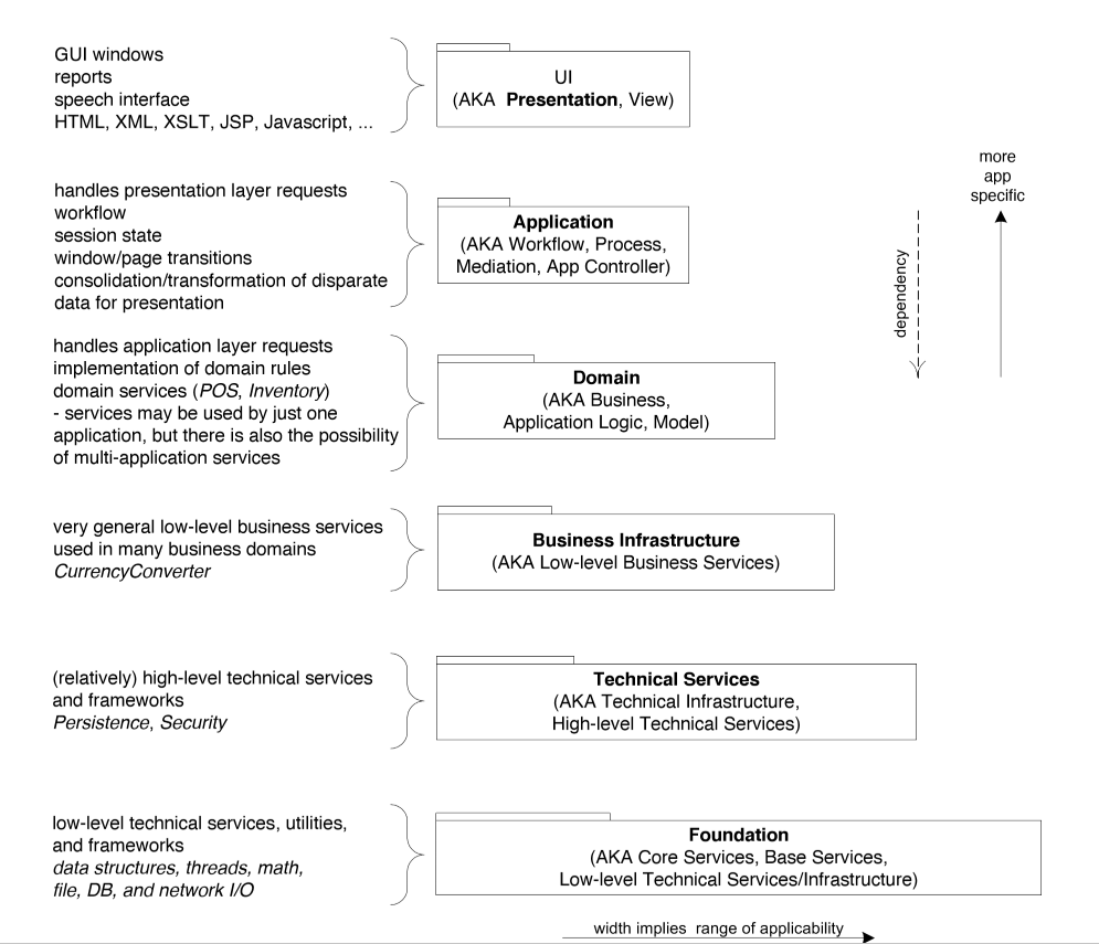
- layers: coarse-grained grouping of classes, packages, or subsystems that has
cohesive responsibility for a major aspect of the system
- very common
- vertical division of a system into subsystems
- e.g.
- UI
- application logic/domain objects
- technical services: general purpose objects/subsystems e.g. interfaces with DB
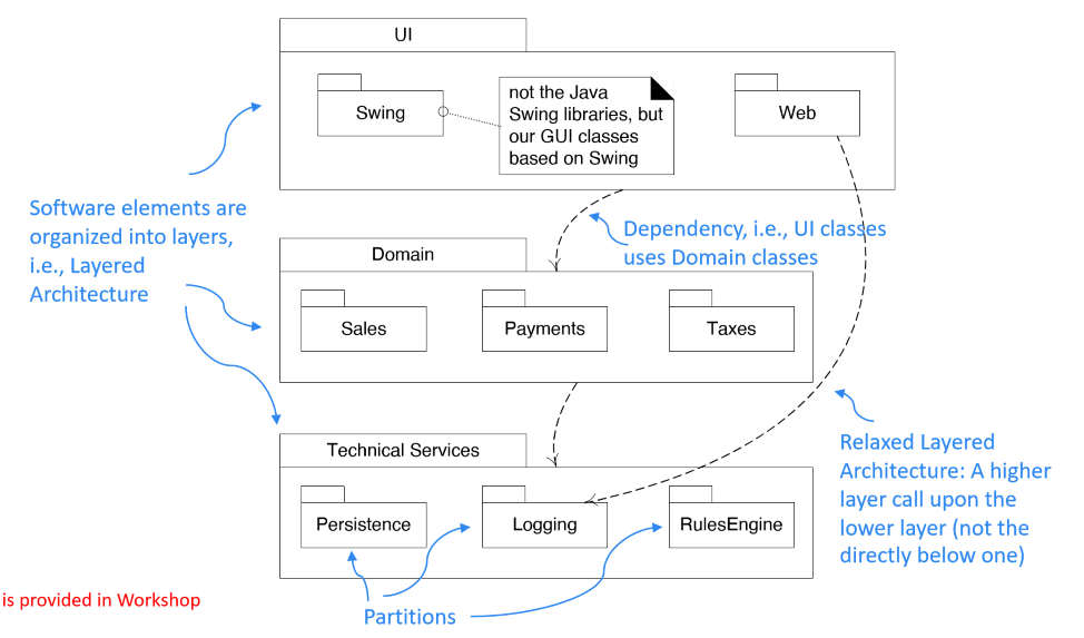
- strict layered architecture: each layer only calls upon the services of the layer directly below it
- common in network protocol stacks
- relaxed layered architecture: higher layer calls upon several lower layers
- common in information systems
- partitions: horizontal division of parallel subsystems within a layer
- benefits:
- prevent high coupling: changes don’t ripple through entire system, and hard to divide work
- promote reuse: application logic is distinct from UI
- ability to change underlying technical services
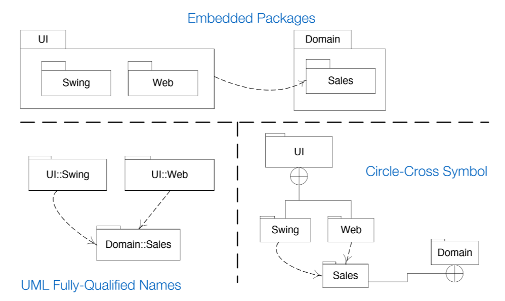
UML Package Diagram
Information Systems - Typical Logical Architecture
UML Component Diagram - Implementation View
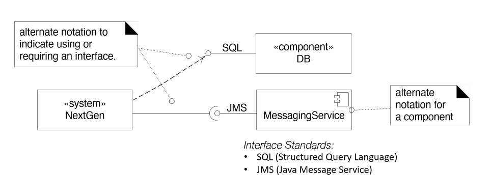
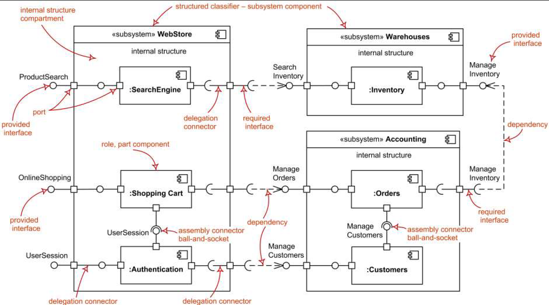
- component: modular part of a system that encapsulates its contents, and is replaceable within its
environment
- can be a class, but can also be external resources (e.g. DB) and services
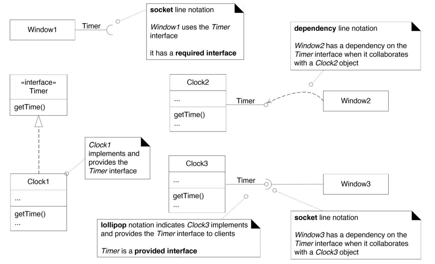
- component diagram: show how to implement software system at a high level
- initial architectural landscape of the system
- defines behaviour: provided/required interfaces
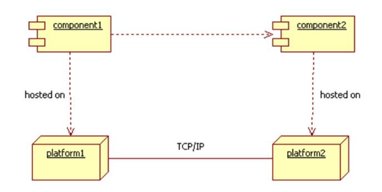
Distributed Architectures
- components are hosted on different platforms and communicate through a network
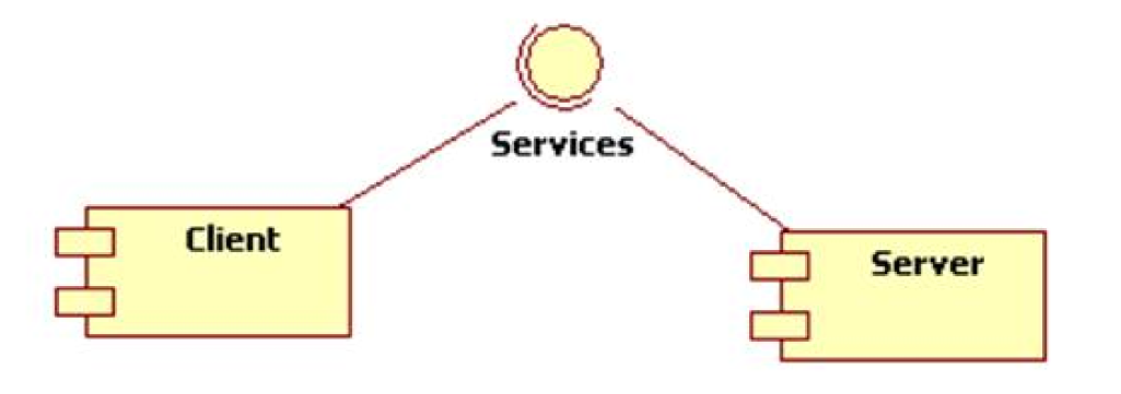
Client-server
- component types: client, server
- server: listens for client requests
- processes requests and responds to client
- can be stateless or stateful
- stateful: allows transactional interactions as sessions
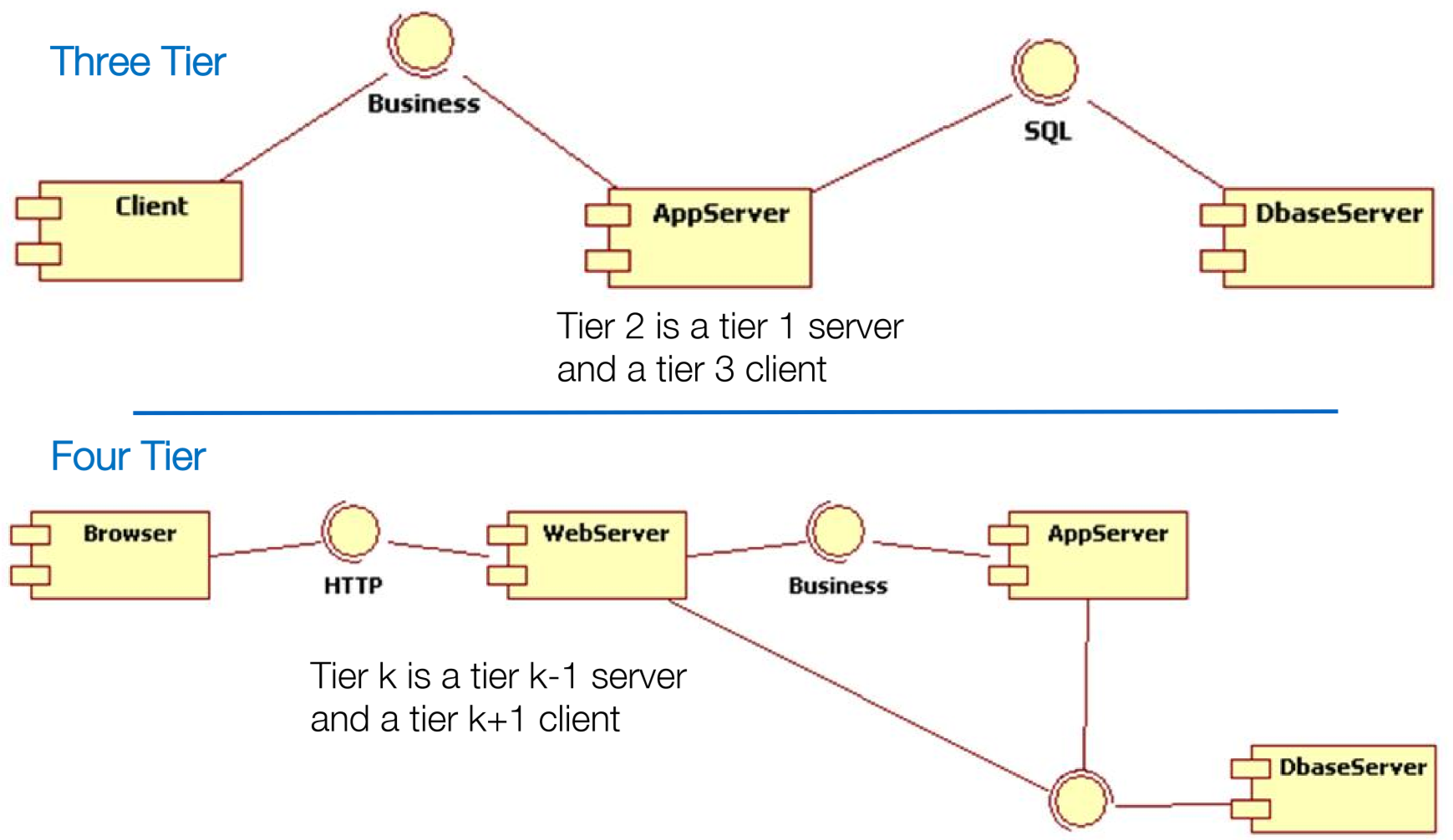
Tiered Client-server
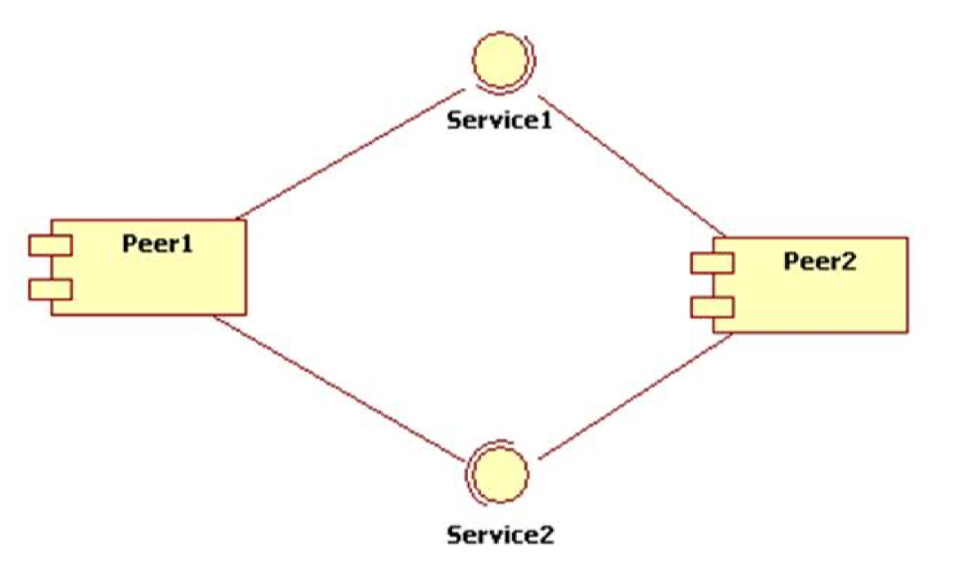
Peer-to-Peer
- all components act as both client and server
Pipeline
- filter perpetually reads data from an input pipe, processes it, then writes the result to an output pipe
- can be static and linear, or dynamic and complex
- used a lot for graphics and signal processing

Architectural Improvement
Strategies
Options that might be considered: buy, build, modify
- Buy: Use COTS
- pros: short development time, low starting cost
- cons: business differences, control over software, long term cost
- Build: build a new system from the ground up
- pros: built-for-purpose for current needs
- cons: high cost, long timeline, high risk for transition
- Modify: modify existing solution
- pros: simpler transition, control of software
- cons: cost and delay tradeoff
- Challenge: planning and executing an acceptable path
Handling issues: some ideas
- responsiveness: host system locally, reduce Internet communications
- reliability: update networking
- modifiability: remove old/redundant systems
- functionality: add high priority, low complexity features
Modelling and Design in the Software Process
- Larman: Chs 4, 8, 12, 14
- Unified Process: iterative/incremental software development
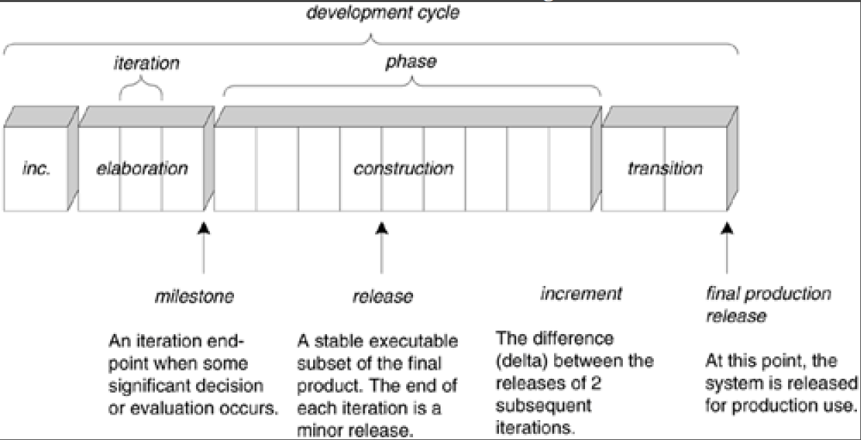
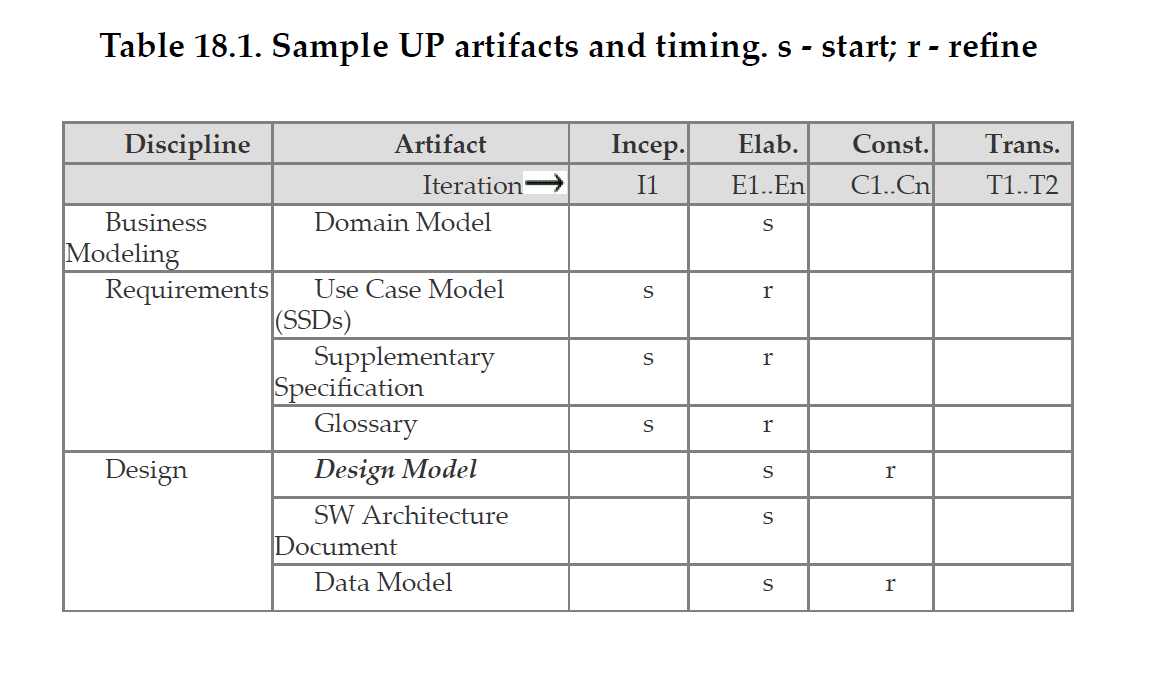
Artefacts
Inception
- inception: initial short step to establish common vision and basic scope
- not the time to detail all requirements, and create high fidelity estimates/plans: this happens in elaboration
- answering questions:
- vision, business case, RoM cost estimates
- buy/build?
- Go/no go?
- Agreement from stakeholders on vision and value?
- how much UML? Probably only simple UML use case diagrams
- should last ~ 1 week
- artefacts should be brief and incomplete
Artefacts
[Bold means mandatory]
- Vision and business case: high level goals and constraints, executive summary, business case
- Use case model: functional requirements. Most use cases name, ~ 10% detailed.
- Supplementary specification: architecturally significant non-functional requirements
- glossary
- risk list and mitigation plan
- prototypes, proof of concept
- iteration plan: what to do in 1st elaboration iteration
- phase plan: low fidelity guess of elaboration phase duration and resources
- development case: artefacts and steps for the project
You’re doing it wrong:
- more than a few weeks spent
- attempted to define most requirements
- expect estimates to be reliable
- defined the architecture
- tried to sequence the work: requirements, then architecture, then implement
- you don’t have a business case/vision
- you wrote all uses cases in detail
- you wrote no use cases in detail
Elaboration
- elaboration: initial series of iterations for
- building core architecture
- resolving high-risk elements
- defining most requirements
- estimating overall schedule/resources
- after elaboration
- core, risky software architecture is programmed/tested
- majority of requirements are discovered/stabilised
- major risks mitigated/retired
- start production-quality programming and testing for a subset of requirements, before requirements analysis is complete
- work on varying scenarios of the same use case over several iterations: gradually extend the system to ultimately handle all functionality required
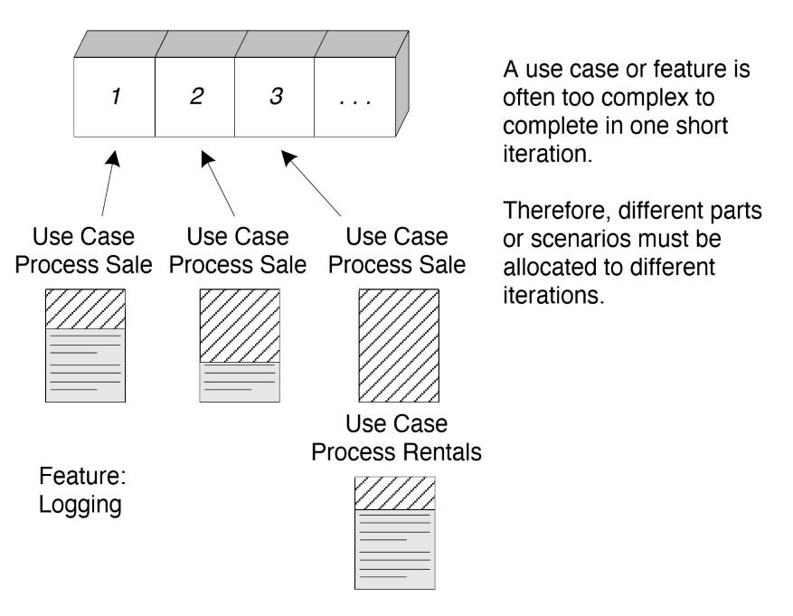
- usually 2+ iterations of 2-6 weeks each, with a fixed end date
- produces the architectural baseline
- test early, often, realistically
- adapt based on feedback from tests, users, developers
Artefacts
- domain model
- design model
- software architecture document
- data model
- use-case storyboards, UI prototypes
You’re doing it wrong:
- more than a few months long
- only has 1 iteration
- most requirements were defined before elaboration
- risky elements/core architecture are not being addressed
- not production code
- considered requirements/design phase, preceding implementation
- attempt to design fully before programming
- minimal feedback/adaptation
- no early/realistic testing
- architecture is speculatively finalised, before implementation
Test-Driven Development and Refactoring
Test-Driven Development
- TDD: development practise in which test code is written before the code that it will test
- acceptance tests at the start of an iteration
- unit tests before the corresponding class is implemented
- promoted in iterative/agile practice
- approach
- alternate between test code and production code
- ensure production code passes tests before proceeding
Advantages
- tests actually get written
- improved programmer satisfaction
- clarification of detailed interface and behaviour
- proven, repeatable, automated verification with a test suite
- confidence to make changes
Unit test the Sale class
- before writing
Sale, write the classSaleTest - choose a method to implement/test e.g.
makeLineItem - implement
SaleTest::testMakeLineItemwhich:- creates a
Saletest item (fixture) - add line items to it with
makeLineItem - ask for the total, verify it is as expected via assertions
- creates a
Refactoring
- refactoring: structured, disciplined method for rewriting existing code, without changing
its external behaviour
- small, behaviour preserving transformations (refactors) are applied, one-by-one
- run test suite to show refactoring did not cause a regression
- series of small transformation can result in major restructuring of code/design for the better with no behaviour change
Code smells
Code smells are suggestive of a need to refactor
- duplicated code
- big method
- class with many instance variables
- class with lots of code
- strikingly similar subclass
- little/no use of interfaces
- high coupling between many objects
Refactorings
There are many named refactorings.
- extract method
- extract constant
- extract local variable
- introduce explaining variable
- replace constructor call with factory method
UML Notes
Class Diagrams
Dependency
- dependency shows coupling between classes
- use the dependency line to depict global, parameter variable, local variable, and static-method dependency between objects
- optional label:
<<call>><<create>>
Composite Aggregation
- aggregation: loosely suggests whole-part relationships
- vague, no meaningful distinct semantics versus a plain association
- use composition instead, where appropriate
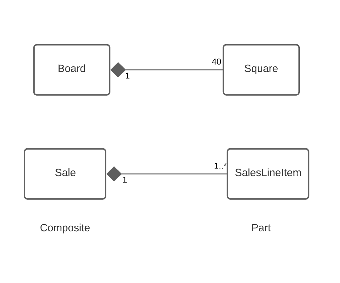
- composite aggregation/composition: strong kind of whole-part aggregation, where a composite aggregates parts, implying:
- an instance of the part (e.g.
Square) belongs to only one composite instance at a time (e.g.Board) - part must always belong to a composite
- composite is responsible for creating/deleting its parts (whether directly, or by collaborating)
- if the composite is destroyed, its parts must be destroyed or attached to another composite
- an instance of the part (e.g.
- Notation: filled diamond on an association line (at the composite end)
- Guideline: association name in composition is always implicitly some variation of “Has-part”
- don’t bother explicitly naming it
